
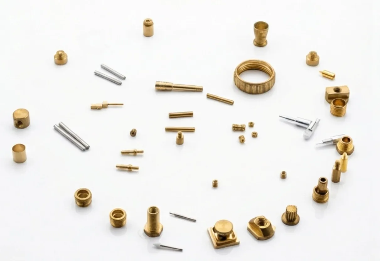
Miniature components carry disproportionate manufacturing risk. As dimensions shrink, burrs, runout, clamping force, inspection uncertainty, and datum errors consume more of the available tolerance. That is why small precision parts are not ordinary components reduced by a scale factor. They need an error budget: a deliberate allocation of variation across material, machining, feature relationships, inspection, handling, and assembly. This protects functional dimensions without imposing unnecessary precision everywhere. It also helps procurement teams compare suppliers and choose between conventional CNC production and a specialised micro-machining route.
Shrinking the CAD Model Does Not Shrink Every Manufacturing Risk
CAD software can reduce a model instantly; manufacturing physics does not follow the same command. A cutting tool still has edge geometry and runout. Inspection equipment still needs access, while a small burr may obstruct a miniature bore or prevent a shoulder from seating.
The mismatch is simple:
- Geometry shrinks, but cutting-edge radius does not shrink proportionally.
- Part mass falls, but clamping distortion can rise.
- Feature spacing decreases, but tool and inspection access remain necessary.
- Tolerance zones narrow, while measurement uncertainty consumes a larger percentage of them.
- Edges become shorter, but burrs may still occupy functional space.
For miniature precision components, engineers must ask whether the entire production and verification system can protect the functional result.
Start the Error Budget with Function, Not with Decimal Places
An effective error budget begins with function. Applying the same tolerance philosophy to every feature can increase cost while leaving the most important relationship poorly controlled.
Identify the One Feature That Controls Assembly
Most small precision parts have one or two characteristics that dominate performance: a bearing diameter, sealing land, thread position, alignment feature, or distance between mating shoulders.
Classify requirements before selecting the machining sequence:
- Function-critical: directly controls motion, sealing, electrical contact, flow, or load transfer.
- Assembly-related: determines fit, alignment, insertion, or clearance with another part.
- Process-supporting: provides a datum or clamping surface.
- General geometry: defines the component without independently controlling function
Separate Functional Variation from General Geometry
Once these groups are clear, tolerance can be allocated selectively. A functional diameter and shoulder may require a controlled single-setup relationship, while a non-mating surface can accept wider variation.
Before assigning aggressive dimensions, designers should review the broader engineering requirements for small precision parts, including functional datums, feature access, material condition, burr control, and inspection planning.
Feature Relationships Consume More Budget Than Individual Dimensions
A diameter can pass inspection while the component still fails in assembly. This happens when the diameter is correct but its position, runout, perpendicularity, or distance from another feature is not.
A Diameter Can Pass While the Component Still Fails
On small precision parts, a diameter, shoulder, axial hole, and thread may each pass inspection, yet accumulated variation can move the mating location beyond the assembly allowance. Follow the functional chain:
Primary datum → functional diameter → locating shoulder → thread → mating component
The drawing must distinguish size tolerance from relational control. Position, runout, and perpendicularity belong only where they reflect function.
Datum Transfers Become More Expensive as Parts Get Smaller
Every re-clamping operation introduces location error. A miniature part may offer only a short land, thin wall, or finished surface that cannot be marked. Critical features should share one setup where practical. If transfer is unavoidable, define how the new datum relates to the original functional feature.
Tool Access Often Sets the Real Limit Before Machine Accuracy Does
Machine positioning specifications alone do not determine manufacturability. The tool must reach the feature with enough rigidity and chip clearance to produce repeatable geometry.
A Small Cutter Is Not Automatically a Precise Cutter
Smaller tools resist less bending force. Long extension, deep pockets, narrow slots, and interrupted cuts amplify tool deflection in micro machining, creating taper, oversized corners, or inconsistent walls.
A tool-access review should check:
- The ratio between feature depth and tool diameter.
- Minimum internal corner radii.
- Space for the holder and tool shank.
- Chip evacuation from narrow or blind features.
- Whether a shorter approach is possible from another direction.
Corner Radii and Groove Widths Must Match Available Tooling
Sharp internal corners create avoidable difficulty. A realistic radius permits stronger tooling and more stable cutting. Groove widths should likewise reflect available inserts or cutters.
Burrs Become Functional Features When the Part Is Small Enough
Burrs are not merely cosmetic. On micro machined parts, they can reduce hole area, alter contact, interfere with a seal, or prevent seating. Aggressive deburring may round a required edge or change a nearby dimension.
Good burr control in small parts begins with three edge decisions:
- The edge must remain functionally sharp.
- The edge requires a controlled break or radius.
- The edge must be burr-free, but minor rounding is acceptable.
Do not replace these decisions with one vague drawing note. Tool exit direction, material condition, and the deburring method determine where burrs form and how safely they can be removed.
Material and Stock Form Affect the Remaining Error Budget
Stock condition affects small precision parts as much as nominal material grade. Bar straightness, diameter consistency, hardness, chip behaviour, and residual stress all influence stability.
Small-Diameter Bar Stock Must Be Evaluated as Part of the Process
In Swiss micro machining, inconsistent bar stock can affect feeding and support before cutting begins. Thin walls may also move as residual stress is released.
For micro turned parts, specify:
- Alloy and temper or material condition.
- Required traceability.
- Starting stock form and relevant size limits.
- Surface condition where it affects feeding.
- Restrictions on material substitution.
Material is an input to the error budget, not a label added after geometry is complete.
Measurement Uncertainty Must Fit Inside the Inspection Plan
A feature is not controlled unless it can be verified. The measurement method needs adequate resolution, access, repeatability, and correlation with function.
A Measuring Device Needs Enough Resolution—and the Right Access
For micro feature inspection, probe size can block access, surface condition can affect optical detection, and thin components can deform under contact force. Fixturing, cleanliness, and orientation also matter.
The inspection plan for micro machining tolerances should answer:
- Can the instrument physically access the characteristic?
- Is its uncertainty suitably smaller than the acceptance zone?
- Does the setup reproduce the functional datum scheme?
Inspect the Functional Chain, Not Every Dimension Equally
Inspection resources should follow risk. First priority goes to fit, sealing, motion, or electrical function. Next come the relationships locating those features, then process-control dimensions, general geometry, and appearance.
This sequence provides better evidence than a long report with little connection to assembly performance.
When Does Precision Machining Become Micro Machining?
No single dimension separates conventional and micro machining. The transition occurs when feature scale changes processing, measurement, or handling.
For small precision parts, warning signs include:
- Tool access is approaching the practical limit of standard cutters.
- Feature size is comparable with tool runout or cutting-edge geometry.
- Re-clamping cannot be performed without losing the functional datum.
- Burrs occupy space needed for assembly or flow.
- Inspection requires dedicated fixturing or non-contact methods.
- Front, back, axial, and radial features must be completed on a small-diameter part.
When these conditions dominate planning, CNC micro machining or precision micro machining may be more appropriate. Qualified precision micro machining services for miniature components can coordinate tooling, setup, inspection, cleaning, and handling as one system.
The Error-Budget Review Before Releasing a Miniature-Part Drawing
Before requesting quotations, use this release check:
- Which feature directly controls fit or function?
- Which datum represents the way the component locates in assembly?
- Which feature relationships should be produced in one setup?
- Can a practical tool reach every specified surface?
- Are internal corner radii compatible with viable tooling?
- Which edges must remain sharp?
- Where could burrs become trapped or obstruct function?
- Can inspection equipment access every critical characteristic?
- Could clamping or measurement force deform the part?
- Is the alloy, condition, and stock form clearly defined?
- How must parts be cleaned and packaged?
- Which requirements are open to DFM review?
This checklist also improves supplier comparison. A capable small precision parts manufacturer should ask about datum logic, tooling access, inspection, and handling—not offer only a machine list and unit price.
Small Components Reward Selective Precision, Not Maximum Precision Everywhere
Strong miniature-part drawings do not demand maximum precision everywhere. They reserve the error budget for features and relationships that determine assembly performance. Tool access, burr direction, material condition, datum continuity, measurement uncertainty, and packaging are considered before production—not after rejection. This makes small precision parts easier to quote, manufacture, verify, and scale. For a useful DFM review, provide the 2D drawing, 3D model, material specification, quantity, and an explanation of the component’s function. That context allows machining and inspection decisions to follow engineering intent rather than isolated decimal places.
